Home >> Products >> Sluice valve
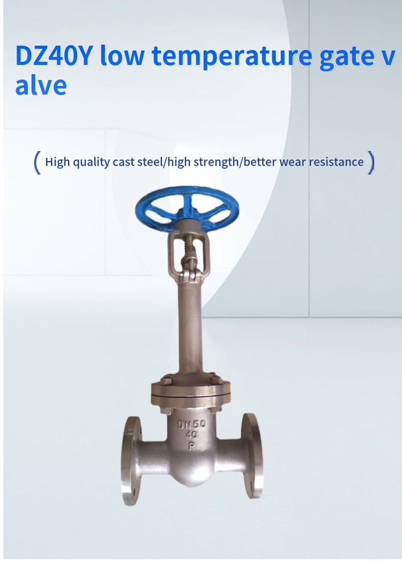
Low temperature gate valve implementation standard design and manufacturing structure length flange size pressure-temperature test - inspection JB/T7749 GB12221 JB79 Gb9131 JB/T9092
Low temperature gate valve pressure test Nominal pressure PN 1.6 2.5 4.0 6.4 10.0 Strength test 2.4 3.8 6.0 9.6 15.0 Water seal test 1.8 2.8 4.4 7.0 11.0 Upper seal test 1.8 2.8 4.4 7.0 11.0 Gas seal test 0.4-0.7
Low temperature gate valve main parts materials and properties body cover valve stem sealing surface gasket packing working temperature applicable medium ZGoCrMNVAI Low temperature high pressure cast steel 1Cr7Ni12 STL/STL 1Cr13/ Flexible graphite Low temperature asbestos PTFE impregnated polytetrafluoroethylene asbestos rope flexible graphite-46 propane/preene Methanol/ethane gas/liquid ammonia LCB ZGoCrMNVAI Low temperature high pressure cast steel -60 LC1 ZGoCrMNVAI Low temperature high pressure cast steel -73 LC2 ZGoCrMNVAI Low temperature high pressure cast steel 1Cr18Ni9Ti-101 LC3 ZGoCrMNVAI Low temperature high pressure cast steel -115 LC4 ZGoCrMNVAI Low temperature and high pressure cast steel -196
Low temperature gate valve main dimensions PN1.6MPa-2.5MPa 1.6MPa DN L D D1 D2 b n-Φd H D0 convex surface method RF DZ40Y-16LCB DZ40Y-16LC1 DZ40Y-16LC2 DZ40Y-16LC3 DZ40Y-16LC4 DZ40Y-16P DZ40Y-16R 20 150 105 75 55 14 4-Φ14 320 140 25 160 115 85 65 14 4-Φ14 350 160 32 180 135 100 78 16 4-Φ18 385 180 40 200 145 110 85 16 4-Φ18 420 220 50 250 160 125 100 16 4-Φ18 540 240 65 265 180 145 120 18 4-Φ18 610 240 80 280 195 160 135 20 8-Φ18 690 280 100 300 215 180 155 20 8-Φ18 780 300 125 325 245 210 185 22 8-Φ18 930 320 150 350 280 240 210 24 8-Φ23 980 350 200 400 335 295 265 26 12-Φ26 1180 400 250 450 105 355 320 30 12-Φ30 1390 450 300 500 460 410 375 30 12-Φ30 1620 500 350 550 520 470 435 34 16-Φ34 1810 500 400 600 580 525 485 36 16-Φ36 1970 550 2.5MPa 20 150 105 75 55 16 4-Φ16 320 140 convex plane method RF DZ40Y-25LCB DZ40Y-25LC1 DZ40Y-25LC2 DZ40Y-25LC3 DZ40Y-25LC4 DZ40Y-25P DZ40Y-25R 25 160 115 85 65 16 4-Φ16 350 160 32 180 135 100 78 18 4-Φ18 385 180 40 200 145 110 85 18 4-Φ18 420 200 50 250 160 125 100 20 4-Φ20 540 240 65 265 180 145 125 22 8-Φ22 510 240 80 280 195 160 135 22 8-Φ22 690 280 100 300 230 190 160 24 8-Φ24 780 300 125 325 270 220 188 28 8-Φ28 930 300 150 350 300 250 218 30 8-Φ30 980 320 200 400 360 310 278 34 12-Φ34 1180 360 250 450 425 370 332 36 12-Φ36 1390 400 300 500 485 430 390 40 16-Φ40 1620 450 350 550 550 490 448 44 16-Φ44 1810 500 400 600 610 550 505 48 16-Φ48 1990 560 PN4.0MPa-10.0MPa 4.0MPa DN L D D1 D2 D6 b n-Φd H D0 concave method MFM DZ40Y-40LCB DZ40Y-40LC1 DZ40Y-40LC2 DZ40Y-40LC3 DZ40Y-40LC4 DZ40Y-40P DZ40Y-40R 20 150 105 75 55 51 16 4-Φ14 330 140 25 160 115 85 65 58 16 4-Φ14 360 160 32 180 135 100 78 66 18 4-Φ18 440 180 40 200 145 110 85 76 18 4-Φ18 455 200 50 250 160 125 100 88 20 4-Φ18 575 240 65 380 180 145 120 110 22 4-Φ20 635 240 80 3103 195 160 135 121 22 8-Φ22 715 280 100 50 230 190 160 150 24 8-Φ22 815 300 125 400 270 220 188 176 28 8-Φ24 965 360 150 450 300 250 218 204 30 8-Φ28 1025 400 200 550 375 320 282 160 38 8-Φ30 1225 450 250 650 445 385 345 313 42 12-Φ34 1440 560 300 750 510 450 408 364 46 16-Φ34 1665 5470 350 850 570 510 465 422 52 16-Φ41 1880 720 400 950 655 585 535 474 58 16-Φ18 2050 800 6.4MPa 20 190 125 90 68 51 20 4-Φ18 330 180 Concave method MFM DZ40Y-64LCB DZ40Y-64LC1 DZ40Y-64LC2 DZ40Y-64LC3 DZ40Y-64LC4 DZ40Y-64P DZ40Y-64R 25 210 135 100 78 58 22 4-Φ23 360 180 32 230 150 110 82 66 24 4-Φ23 410 180 40 240 165 125 95 76 24 4-Φ23 480 220 50 250 175 135 105 88 26 4-Φ23 585 240 65 280 200 160 130 110 28 8-Φ23 690 240 80 310 210 170 140 121 30 8-Φ23 745 280 100 350 250 200 168 150 32 8-Φ25 885 300 125 400 295 240 202 176 36 8-Φ30 985 360 150 450 340 280 240 204 38 8-Φ34 1050 400 200 550 405 345 300 260 44 12-Φ34 1240 450 250 650 470 400 352 313 48 12-Φ41 1460 560 300 750 530 160 412 364 54 16-Φ41 1670 5640 10.0MPa 25 210 135 100 78 58 24 4-Φ18 365 200 Concave method MFM DZ40Y-100LCB DZ40Y-100LC1 DZ40Y-100LC2 DZ40Y-100LC3 DZ40Y-100LC4 DZ40Y-100P DZ40Y-100R 32 230 150 110 82 66 24 4-Φ23 420 200 50 250 195 145 112 88 28 4-Φ25 630 240 65 280 220 170 138 110 32 8-Φ25 700 240 80 310 230 180 148 121 34 8-Φ25 760 280 100 350 265 210 172 150 38 8-Φ30 900 280
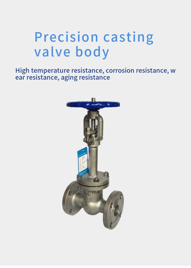
1. In order to prevent abnormal pressure increase in the middle cavity, pressure relief holes are set up on the inlet side of the ram
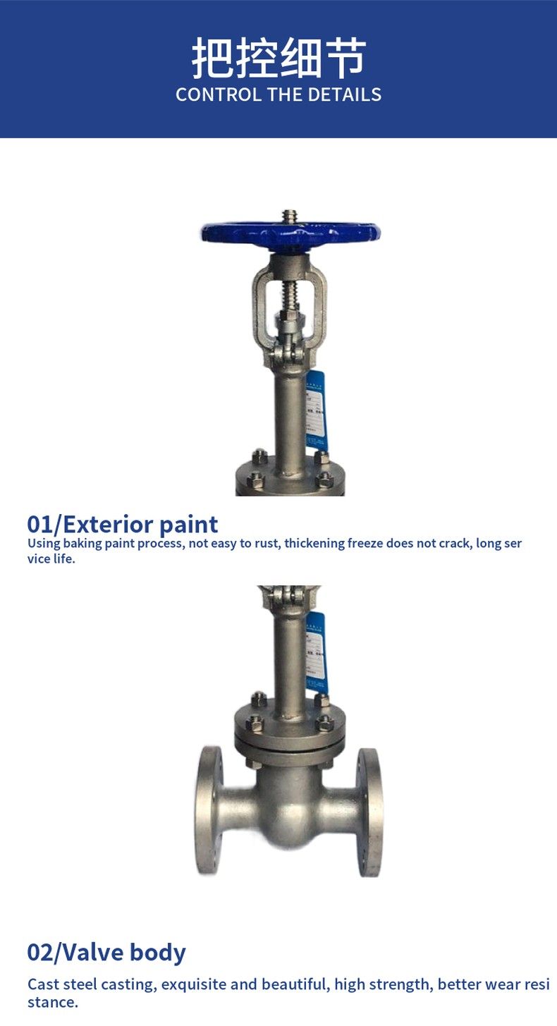
2, according to the working temperature of the valve to determine the top length of the valve cover, to ensure the reliable sealing of the valve stem packing
3, according to the working temperature reasonable selection of packing, gasket and other parts of the material
4, strictly control the chemical composition of the material and low temperature impact toughness and other mechanical properties indicators
5, the use of a variety of pipe flange standards and sealing surface types, suitable for various engineering needs
